When reinstalling the system or Solidworks, you want to save your personal settings, in order to restore them later. Also it is convenient when transferring the Solidworks settings (toolbars, menus, hot keys) to another computer. The utility "SolidWorks Copy Settings Wizard", which is part of SolidWorks, will help us in this. The utility is on the path

"C:\Program Files\SolidWorks\SolidWorks\setup\i386\copyoptwiz.exe"

or in the "Start" menu - "All Programs"
Solidworks - утилита копирования и воcстановления настроек в Windows
Solidworks 2012 - Copy Settings Wizard.


In versions of Solidworks 2015 and later, you can run the utility directly from Solidworks.


Launch the "Solidworks Copy Settings Wizard".
Solidworks - The startup window of the utility for copying and restoring settings in the Solidworks menu


Choose Save Settings


Choose which settings you want to save and the location of the settings file. Done.


Restoring settings is done in a similar way.


Click "Restore Settings" - "Next"


We show the settings file and choose which settings to import.
Pay attention to the possibility of importing settings settings in different versions of Solidworks. The screenshot shows the restoration of the Solidworks 2016 settings using the utility from the Solidworks 2017 suite.


Just in case, put a check mark "Create backup copy" - "Done".


All. You can run Solidworks and enjoy the familiar interface.
If you tick the "Backup current settings" checkbox, the utility will save the file starting with the words "backup" before restoring the setting,
Solidworks - Файлы настроек Solidworks


You can restore Solidworks 2017 settings to Solidworks 2016 or earlier. Remember to change the location of toolbars in newer versions.

A file with saved settings is the most ordinary reg-file only with the extension "sldreg"


Thus, you can import the Solidworks settings even without the "Solidworks Copy Settings Wizard" utility, by simply entering data into the registry. This can be done by double clicking on the file and confirming the data entry in the registry, or through the Windows regedit utility.

Of course, you can restore settings to other Solidworks versions via the "Solidoworks Settings Copy Wizard", but if you want, you can change the year in the reg file to the required ones and also make the settings in other versions. For example, opening a file with a notebook and making a replacement for "2016" for "2015" we get the file of the settings Solidworks 2015.

Attention !!! When migrating from Solidworks 2008 or lower to Solidworks 2009 or higher, you should note that the default installation path has changed:

"C:\Program Files\SolidWorks\SolidWorks" - Solidworks 2008 or lower

"C:\Program Files\SolidWorks Corp\SolidWorks" -  Solidworks 2009 or higher.

There is one interesting feature in Solidworks that I did not find in the Solidworks help or was looking badly :). Use one sketch in different elements. To do this, select the sketch by clicking the left mouse button on the sketch, (first open it in the tree) and click on the desired element: draw, cut, etc. After that, enter the parameters and confirm. As a result, you will get an element that is created with a sketch from another element. The icon for such a sketch, used in several elements, looks like a sketch with the palm opened under it, similar to the common folders in Windows.
Solidworks общий эскиз


You can use sketches of different elements in other elements repeatedly.
For example, we'll make a figurine on the panel, we'll simulate it the way it is done in the production: we make the workpiece and then milling it along the contour.
Solidworks общий эскиз

Use the "Swept Cut"


Solidworks общий эскиз - заготовка

Specify the profile

Solidworks общий эскиз

and the trajectory of the cutout

Solidworks общий эскиз

Repeat our actions for the other side of the workpiece

Solidworks общий эскиз


Solidworks общий эскиз


As a result, we received a parametric panel.


Solidworks общий эскиз в параметрической филенке


See this video.


Worcester Polytechnic Institute


Pioneering First Robotics Engineering Degree with SOLIDWORKS Education Edition
Founded in 1865 to create and convey the latest science and engineering knowledge in ways that are most beneficial to society, Worcester Polytechnic Institute (WPI) has grown to become one of the world’s leading universities, and to support its Robotics Engineering Program, WPI chooses to provide its students with SOLIDWORKS Education Edition design software.

Catrike.com
Hamex Hamermolen, Dinnissen Process Technology
 Dinnissen Process Technology uit Sevenum staat bekend om haar innovatieve technieken om poeders en korrels te verwerken tot onder andere voedingsmiddelen, veevoeders, medicijnen en chemische producten. Voor het ontwerp van haar innovatieve machines en complete productieprocessen maakt Dinnissen gebruik van het bekende 3D ontwerpprogramma "SOLIDWORKS". De 2.7 Miljoen gebruikers van dit ontwerpprogramma starten voortaan op met een afbeelding van de Hamex Hamermolen van Dinnissen. Dinnissen is zeer vereerd dat Solids Works haar foto selecteerde om vorm te geven aan de uitstraling van de nieuwste versie van haar ontwerpprogramma.

Ontwerp Dinnissen gekozen voor beeldvorming belangrijk ontwerpprogramma
Dinnissen Process Technology ontwikkelt en fabriceert machines en complete productielijnen om poeders en korrels te verwerken tot allerlei producten in de onder andere de food, feed, farmacie en chemie. Zo is Dinnissen een bekende leverancier van technieken om babymelk, oploscacao, waspoeders, diervoeders en muesli te produceren. Voor het ontwerpen van al deze technieken maken de ontwikkelaars bij Dinnissen gebruik van het 3D ontwerpprogramma SOLIDWORKS. Daar sprong het vooruitstrevende ontwerp en de uitstraling van de machines van Dinnissen zo in het oog dat het bedrijf werd gevraagd een afbeelding te leveren voor het opstartscherm van de allernieuwste versie van het softwareprogramma. SOLIDWORKS koos voor een afbeelding van de Hamex Hamermolen met automatische zeefwisselaar van Dinnissen. Met deze innovatieve maalinstallatie kunnen fabrikanten hun producten nog sneller malen en bovendien supersnel overschakelen naar een andere maalfijnheid van hun producten. Wouter Kuijpers van Dinnissen is zeer vereerd dat ons ontwerp voor een innovatief product het symbool wordt voor één van de belangrijkste 3D ontwerpprogramma's die wereldwijd worden gebruikt. 2.7 Miljoen engineers maken zo kennis met ons bedrijf.

3D ontwerp voor betere en snellere ontwerpen van nieuwe producten
Een 3D ontwerp programma als SOLIDWORKS is voor bedenkers van nieuwe technieken erg belangrijk. Een 3D ontwerp geeft klanten al vroeg in het ontwerpproces een nauwkeurig inzicht in de oplossing die voor hen is bedacht. Het ontwerpproces bij Dinnissen verloopt door het gebruik van 3D ontwerpen 25% sneller en doelgerichter. Een 3D ontwerp van een nieuw te bouwen machine biedt ook veel voordelen voor de productie. De efficiency bij Dinnissen is op deze afdeling met 15% verbeterd. 
Dresser Inc

Chris Wilson, Orwell offshore Ltd

Trakka
Today, Trakka’s products are more defined and production based from ideas that have evolved over the decades. With 17 variations of pop-top campervans, van based & coach built motorhomes on offer, the team now attend approximately 10 exhibitions a year.
Deutsches SOFIA Institut


The scientific operations of the Stratospheric Observatory for Infrared Astronomy (SOFIA) is coordinated by the German SOFIA Institute (DSI), which is based at the University of Stuttgart, and the Universities Space Research Association (USRA) in the United States. Together they empower students with SOLIDWORKS Research Edition to design and optimize SOFIA's systems.


Underwater camera Zuccarini 
 Watershot, Inc., designs and manufactures underwater housings for 35 mm still, video, and 16 mm/35 mm film cameras. The demand for more sophisticated underwater camera housings – such as the underwater film housings produced for Zuccarini Films, Inc., a leading underwater cinematographer – compelled the company to investigate ways to improve design efficiency and accuracy.
RUSSELL MINERAL EQUIPMENT


Parrot Bebop 2
The Parrot Bebop 2 is sturdy and reliable. Designed to fly indoors and outdoors, it's the first leisure drone weighing less than 500 g with a 25-minute battery life. With the Parrot Cockpitglasses, discover FPV (First Person View) and view all your flights as if you were in the cockpit! Designed to be easily transported, the Parrot Bebop 2 will go with you wherever and whenever you want for you to capture your best moments from the sky.
It is necessary to make the transition from a round tube to a square of sheet metal. Let us consider the principle of constructing such scans from sheet metal. In order to get a sweep of it you need to build it using the tool "Element by the bend cross-sections". It is located in the Sheet Metal toolbar, in the Insert menu - Sheet Metal, on the Sheet Metal tab, or you can take it to the right place when setting up the Solidworks interface.


Solidworks - "Элемент по сечению сгиба" в меню "Вставка"
"Элемент по сечению сгиба" в меню "Вставка"

Solidworks - "Элемент по сечению сгиба" в меню "Настройка"
"Элемент по сечению сгиба" в меню "Настройка"
The construction scheme is as follows:

We construct a sketch of a circular non-closed section, the gap is necessary to obtain a sweep. The gap must be dimensioned (generally a fully defined sketch reduces the probability of error), you can make 1mm or less.
Solidworks - Эскиз круглого незамкнутого сечения
Sketch of a circular open section


We create a plane on which the profile of the second section will be located and on it we draw an open quadratic profile, with a gap. Gaps can be linked either by an equation or by using separated values (more conveniently).
It is necessary to round the corners of the square section, otherwise Solidworks will give an error.
Solidworks - Эскиз квадратного незамкнутого сечения
Sketch of square open section
After that using the Solidworks tool "Element for the bend cross sections", create a transition from the sheet metal, select the first profile, then the second one and specify the thickness of the metal. Take into account the direction of the thickness, because if the direction is inside, the thickness should be less than the radius of the fillets. The direction must also be considered based on the specified dimensions, a fixed internal or external dimension is needed. Confirm the execution of the command and get a transition from sheet metal.
Solidworks - Переход из листового металла
The resulting transition from sheet metal

There is an interesting point, there are no sweeps in the configurations. You can create it manually and highlight the sweep element in the build tree.
Solidworks - Развертка перехода
Flat Pattern
But when creating a drawing, this configuration of "SM-FLAT-PATTERN" containing the part in the expanded state is created automatically.

Now let's proceed to export the sweep to the dxf format, for the subsequent cutting on plasma cutting, laser or waterjet. To avoid errors with scaling, I recommend exporting directly from the part. To do this, activate the configuration with a scan, click on the flat surface with the right button and select "Export to DXF / DWG", select the save location and file format. In the same window, you can configure the export options in dxf / dwg, for this click the "Options" button. From the settings I recommend turning on "Export all splines as polylines" and "Enable connection", the necessary gap clearance is selected by yourself.
Solidworks- Настройка экспорта в dxf/dwg
Setting up export to dxf / dwg

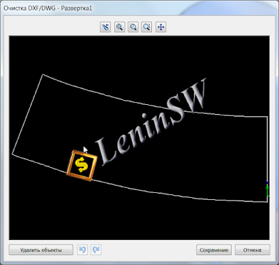
After the export is confirmed, the "DXF / DWG Clear" window opens, in this window you can delete unnecessary holes or other elements.
Solidworks - Очистка dxf
Cleaning

 If necessary, you can undo the changes. After cleaning, click "OK" and the dxf / dwg file is created in the location you specified.

Just sweep can be done without activating the flat state. To do this, select the unfoldable surface and save it as dxf. Solidworks add the "Sweep" before the name of the saved part. Further as in the previous case.

The other way is even simpler, right-click on the Sweep in the design tree and select "Export to DXF / DWG", further as described above.

And the easiest way, just save the part as dxf / dwg, the rest as in the previous cases.

And finally, the most complex and most (as it turned out) common option: saving from the drawing.
The bottom line is simple, you insert a sweep in the drawing sheet and save it in dxf / dwg. In addition to more actions, this option carries a very unpleasant feature: distortion of the scan scale. If the scale of the sheet coincides with the scale of the drawing view, there will be no scale distortion. In other cases, there are different options and this is the topic of a separate article. Therefore, I recommend exporting from the model, there will be no problems with scaling.
Solidworks has an excellent feature for isolating parts and assemblies designed to simplify the modeling and design of drawings. Many do not know or do not use this functionality. On the video you can see the use of isolation in Solidoworks.


Solidworks Help


The Isolate command sets all components except the selected ones to be hidden, transparent, or wireframe, enabling you to focus on the selected components.

You can isolate parts or subassemblies, making it easier to edit them in the context of the assembly. You can also isolate components that share a mate.

You can use the Isolate popup toolbar to change the visibility of the hidden components to Wireframe, Transparent, or Hidden. The transparency usually used when editing a component in the context of an assembly is not used when Isolate is active.

Before you exit Isolate, you can save the display characteristics to a new display state, which you can access from the ConfigurationManager. If you do not save, the display returns to its original state without any permanent changes.
When you select Hidden, you can match the FeatureManager design tree to the graphics area by selecting Filter Hidden/Suppressed Components in Filter .

To isolate components that share a mate, right-click the mate in the FeatureManager design tree and click Isolate.


Often there is a need to make the mating of parts, with a surface or edge that is not visible. The function "Isolate" is not always convenient to apply. Fortunately, it is possible to specify the required element for pairing, even if it is not visible.


Solidworks Help.
Selects entities that are hidden by other entities.
To select hidden items:
  1. In a part or assembly document, right-click the model in the graphics area and choose Select Other menu_Select_Other.gif.
    • The pointer changes to pointer_Select_Other.gif and a box appears with a list of entities (faces, edges, subassemblies, etc.) that lie beneath the pointer, in the order in which they are encountered. An icon displays the type of entity (face, edge, etc.).
    • Hover the pointer over items in the list to highlight them in the graphics area.
    • To scroll through the list, press Tab or roll the middle mouse button.
    • You can right-click on the model to hide faces, revealing other hidden faces and edges.
  2. Click in the list or the graphics area to select an entity.
    fund_Select_Other.gif


    If the first time in the list is not the desired item, cancel and select the area closest to the desired item.
    Regardless of which measurement system we draw, Solidworks allows calculations in both the metric and Imperial systems. To do this, simply add a unit of measure after the value. For example, in the metric systems by entering 100ft, we get a size of 30480 mm. Similarly with the Imperial and US customary measurement systems, by entering 30480 mm, we get the equivalent in feet or inches . Also in metric systems, you can just write 25 cm and this will translate into 250 mm.


    Available values

    • m - metre (1000 mm)
    • cm - centimetre (100 mm)
    • um - micrometre (0,001 mm)
    • nm - nanometre (0,000001 mm)
    • A - angstrom (0,0000001 mm)
    • ft - foot (304,8 mm)
    • in - inch (25,4 mm)
    • mil - mil (0,0254 mm)


    Here is a quick video demonstrating this functionality:


    In Solidworks, you can simplify the interfacing of components. Press and hold "Alt" to move the mouse pointer to the desired surface, press the left mouse button and drag to the second surface for the auto-conjugation. A pane will appear with the default interface already selected for these surfaces. Those. if the surface is flat, then the automatic interface is a coincidence, if the surface is cylindrical, then the automatic interface is concentric. There are other options for automatic pairing


    (SmartMates Procedures)
    Desired Mate Action
    What to Do
    Mate two components already in the assembly. Press Alt and drag one component onto another.
    Mate a new component while adding it to the assembly.Drag a part from another window onto another part in the assembly.

    • From a part file: Select an entity and drag.
    • From an assembly file: Hold down Shift, then select an entity and drag.
    Fully mate a commonly-used component while inserting it in the assembly.Drag a part with mate references from Windows Explorer or the Design Library into the assembly. This method can fully mate a new component, but you must set up mate references beforehand.

    Types of SmartMates
    The mates added by the SolidWorks application depend on the situation.
      In most cases, the application creates one mate. The type of SmartMate created depends on the geometry used to drag the component, and the type of geometry onto which you drop the component.
      The application creates multiple mates under certain conditions:
    • If the application finds circular edges to mate, it creates a peg-in-hole SmartMate.
    • If the application finds circular edges and a circular pattern that matches on both components, in addition to the peg-in-hole SmartMate, it adds a concentric mate to line up the patterns on flanges ( useful for pipe fittings).


      For more information on auto-mates, see Solidworks Help.

      When filling in those. requirements it is necessary to put a symbol of diameter, plus-minus, degree, etc. Adding using the symbol table is not fast. And in the design it is desirable to optimize the routine work, it means the design of the drawings.
      For example, to insert a symbol from a symbol table, you need to go through three menus, and then select the one you need from a large number of fonts. Yes, there is a huge choice in the symbol table, but the designer does not need technical requirements for it, it needs quite a few special symbols.
      Solidworks - Добавление спецсимволов
       Adding special symbols


      Solidworks - Библиотека обозначений
      The Symbol Library
      Solidworks - Таблица символов
      The Symbol Table


      If you apply a dimension, the symbol of diameter and degree can be added quickly.
      Solidworks - Добавление диаметра в размер
      Adding a diameter

      then in the notes so simply does not work. It will be necessary to make quite a large number of mouse clicks until you get to the required symbol. Fortunately, there is the ability to quickly enter special characters using ALT-codes. To enter a special character, press and hold ALT to enter the numeric character code.
      List of most frequently used:


      English keyboard!
      (±); input: ALT+0177
      (°); input: ALT+0176
      (²); input: ALT+0178
      (³); input: ALT+0179 
      (Ø); input: ALT+0216
      (ø); input: ALT+0248 


      Of course, on this list of ALT-codes is not limited, the full list can be found in nete, on the same wikipedia.
      I think that to speed up the input to remember a few digital codes will not be difficult, try. Of course, you can enter some special characters using internal Solidworks codes such as <MOD-DIAM>, <MOD-DEG>, <MOD-PM>. What is the analog of diameter, degree and plus or minus. But the ALT code is shorter and easier to type.
      The spring is one of the standard products, which is often used, but it is desirable to automate the simulation. Fortunately, there are enthusiasts who undertake this work. Macro for creating springs of tension and compression "SpringSW" - author of Shvg. To use the macro, you must add it to add-ins. To do this, open "SpringSW.dll", then "Spring" will appear in the "Tools" menu. Use the look at the video. For the coupling of the spring into the part, there is an axis "Axis1". The build tree is hidden, but it's even better. The spring has several configurations in different states: compressed, working, etc. The macro allows you to build compression springs and also to edit the data. Easy and convenient to use.


      Administrator rights are required to install and use the macro. You can change the shortcut to start


      Download macro с SpringSW

      Search This Blog

      Избранное сообщение

      SOLIDWORKS 2018 Import and Export Hole Wizard Data with Excel

      You can now import and export Hole Wizard data with Excel files in the Configuration tool with SOLIDWORKS 2018.  Previously this could only ...

      Popular posts